A simple battery charge controller. Battery charge controller. Solar battery voltage
And what is it for?
Why do you need a charge controller?
A charge controller is a device that automatically regulates the level of current and voltage from a source (such as solar panels) to ensure that the batteries are charged, thus protecting the batteries from damage.
Is it possible to do without a charge controller?
Having some experience with electrical appliances, knowing how to use a voltmeter and ammeter, having carefully studied the battery instructions for charging and discharging characteristics, you can certainly do without a charge controller.
The battery charge is determined by the voltage between the terminals. Nothing prevents you from connecting a source (for example, solar panels) directly to the battery, while controlling the voltage at the terminals and the current from the source (so that the battery is not damaged). When the voltage at the terminals corresponds to the maximum charge, you just need to turn off the source. This will charge the battery to 60-70% of its maximum capacity. In order to charge it to 100%, the battery needs to stabilize - for some time after reaching the maximum voltage, continue charging at this voltage.
With this method of charging the battery, there is a high probability of a decrease in the nominal capacity (due to systematic undercharging) or failure due to high current or voltage. That is why various charge controllers are used.
What are charge controllers?
There are mainly three types of charge controllers - on / off controller, PWM (PWM) controller and MPPT (ТММ) controllers. What are their features and how they differ:
on/off charge controller
this device performs the function of disconnecting the batteries from the source when a certain voltage is reached. This type of controller is practically not used today. This is the simplest alternative to the manual battery control we talked about earlier.
PWM (PWM) controller
This device is already a more advanced option for charging batteries, since it automatically controls the level of current and voltage, and also monitors the onset of the maximum voltage. After the maximum voltage is reached, the PWM controller holds it for a while to stabilize the battery and reach its maximum capacity. As a rule, such controllers are inexpensive and can suit simple solar systems.
You can read about how to choose such a controller here -
MPPT (ТММ) controllers
This controller is the most modern solution for solar power plants. Solar panels produce power at a strictly defined value of current and voltage (CVC curve - current-voltage characteristic) - this mode is called the Maximum Power Point (TMP). MPPT the controller allows you to track this point and can make the most efficient use of the energy of the solar panels, which in turn increases the speed of charging the batteries. Such controllers can charge batteries (battery bank) 30-40% more efficiently, therefore, for backup and autonomous solar power plants, the use of just such controllers becomes the most profitable, despite their high cost relative to PWM controllers.
Which charge controller to choose?
When choosing a controller for a solar system, you first need to understand the scale of the system itself. If you are assembling a small solar system to provide the most necessary household appliances with electricity (from 0.3 kW to 2 kW), then it is quite possible to get by with a properly selected PWM controller. If we are talking about a stand-alone system, a backup system, or perhaps a system compatible with mains electricity, then in this case a good MPPT controller is indispensable.
The charge controller is a very important part of the system in which the electric current is generated by solar panels. The device controls the charging and discharging of batteries. It is thanks to him that the batteries cannot be recharged and discharged so much that it will be impossible to restore their working condition.
Such controllers can be made by hand.
Homemade controller: features, components
The device is intended for operation only, which creates a current with a force not exceeding 4 A. The capacity of the battery, which is charged, is 3,000 Ah.
For the manufacture of the controller, you need to prepare the following elements:
- 2 chips: LM385-2.5 and TLC271 (is an operational amplifier);
- 3 capacitors: C1 and C2 are low power, have 100n; C3 has a capacity of 1000u, rated for 16V;
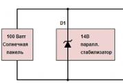
- 1 indicator LED (D1);
- 1 Schottky diode;
- 1 diode SB540. Instead, you can use any diode, the main thing is that it can withstand the maximum current of the solar battery;
- 3 transistors: BUZ11 (Q1), BC548 (Q2), BC556 (Q3);
- 10 resistors (R1 - 1k5, R2 - 100, R3 - 68k, R4 and R5 - 10k, R6 - 220k, R7 - 100k, R8 - 92k, R9 - 10k, R10 - 92k). All of them can be 5%. If you want more accuracy, then you can take 1% resistors.

What can replace some components

Any of these elements can be replaced. When installing other circuits, you need to think about change in capacitance of capacitor C2 and selecting the bias of the transistor Q3.
Instead of a MOSFET transistor, you can install any other. The element must have a low open channel resistance. Schottky diode is better not to replace. You can install a conventional diode, but it must be placed correctly.
Resistors R8, R10 are 92 kOhm. This value is non-standard. Because of this, such resistors are difficult to find. Their full replacement can be two resistors with 82 and 10 kOhm. Need them turn on in series.
Read also: Features of solar fountains
If the controller will not be used in an aggressive environment, you can install a tuning resistor. It allows you to control the voltage. In an aggressive environment, he will not work for a long time.
If you need to use the controller for stronger panels, you need to replace the MOSFET transistor and diode with more powerful counterparts. All other components do not need to be changed. It makes no sense to install a heatsink for 4A regulation. By installing a MOSFET on a suitable heat sink, the device will be able to work with a more productive panel.
Principle of operation
If there is no current from the solar battery, the controller is in sleep mode. It does not use any of the watts from the battery. After sunlight hits the panel, electric current begins to flow to the controller. He must turn on. However, the indicator LED, together with 2 weak transistors, turns on only when the voltage reaches 10 V.
After reaching this voltage current will flow through the schottky diode to the battery. If the voltage rises to 14 V, the amplifier U1 will start to work, which will turn on the MOSFET transistor. As a result, the LED will go out, and two non-powerful transistors will close. The battery will not charge. At this time, C2 will be discharged. On average, it takes 3 seconds. After the capacitor C2 is discharged, the hysteresis U1 will be overcome, the MOSFET will close, and the battery will begin to charge. Charging will continue until the voltage rises to the switching level.
Charging happens intermittently. At the same time, its duration depends on what the charging current of the battery is and how powerful the devices connected to it are. Charging continues until the voltage reaches 14 V.
The circuit turns on in a very short time. Its inclusion is affected by the charging time of C2 by the current, which limits the transistor Q3. The current cannot be more than 40 mA.
Frequently asked questions by newbies about which controller to buy for a particular battery. And what do amps mean in the characteristics of the controller. Let's in this thread I will try to tell you separately what kind of amps it is. Let's start with, and perhaps the most important thing, that the amperes that are indicated on the controller are different concepts for different manufacturers of both solar and wind turbine controllers. All manufacturers interpret data in their own way, hence many people get confused and misunderstood when choosing a controller. Below I will try to give examples and ways to avoid problems in the future.
The first thing we'll start with is:
- A charge controller is a device that controls the process of charging a battery, they are divided into two popular categories:
1. what is PWM- this is a pulse-width modulation controller, its task is to charge the battery with pulses, controlling the battery voltage level: in this case, charge control can be carried out rigidly (in other words, allegedly in automatic mode). Or in manual mode, where you can manually set the required voltage to charge the battery. Read the instructions for the controller. I recommend choosing a controller with manual input. And rare are controllers with preset values. A rarity, because nowadays often such controllers come with the ability to select manual mode. This controller is good because almost no energy is required for its operation, and the consumption of such controllers rarely exceeds 100 mA.
They are less attached to bad weather, and if there is a current of at least 10 mA at the input, and the voltage exceeds the battery voltage, the controller will charge. Also, I will attribute the recently revealed effect of rapid aging of the panel to the pluses, due to the degradation of cells from temperature. With these controllers, the power taken from the panels is from 0 to 80% as the battery is charged. At the same time, the solar panels heat up less, and the elements do not suffer degradation due to overheating even on the hottest day, since the temperature does not rise above +60-70 degrees Celsius. Of the pluses, stable operation in any weather can be noted!
2. what is MPPT- This is a controller that has the function of tracking the maximum point of the solar panel, in Russian - these are OMTP controllers. In English it sounds like maximum power point tracking.The task of this controller is to squeeze all the juice out of the solar panel, and at the same time receive from the solar power plant or wind generator, depending on the type of controller, all the peak power that your system is capable of. Sounds great, but is it really so, you can read . There are controllers that can limit the charge current, but this is rare, you need to read the description of the controller. One example of a controller with charge current limitation is a solar charge controller from Sibkontakt SKZ 40
So, what is the current that is indicated on the controllers. Again, for each controller, the current that is indicated can have a completely different value, let's look at the main ones:
- the maximum current can be specified - at which the controller will either fail with a long load, or the protection will work and the battery will stop charging from the controller until it is rebooted, or a new daylight day comes.
- the current may be short-term or in other words recommended below, but during bursts the controller will continue to work.
- the current can be specified as the battery charge current, i.e. it is not recommended to connect batteries above this current. Otherwise, the controller may not withstand
- the current can be the nominal recommended, but not the maximum, for example, old tracers can be included here, which have a margin for recoil current, but the controller heats up well, so additional cooling is required.
In most modern budget segment controllers, the maximum current is indicated, that is, in total, the connected sources should not cross it, and even reach some, otherwise the protection will work.
The principle of operation of controllers for charging solar panels, the device, what to consider when choosing
In modern solar power plants, different schemes for connecting current sources are used to transfer the generated electricity to working batteries. They use different algorithms, are based on microprocessor technologies, are called controllers.
How solar charge controllers work
The electricity generated by the solar battery can be transferred to storage batteries:
2. through the controller.
In the first method, the electric current from the source will go to the batteries and will increase the voltage at their terminals. At first, it will reach a certain, limiting value, depending on the design (type) of the battery and the ambient temperature. Then it will overcome the recommended level.
At the initial stage of the charge, the circuit works normally. But then extremely undesirable processes begin: the continued supply of the charging current causes an increase in voltage in excess of the permissible values \u200b\u200b(of the order of 14 V), an overcharge occurs with a sharp increase in the temperature of the electrolyte, leading to its boiling with an intense release of distilled water vapor from the cells. Sometimes until the containers are completely dry. Naturally, the battery life is sharply reduced.
Therefore, the problem of limiting the charging current is solved by controllers or manually. The last way: to constantly monitor the voltage value on the instruments and switch the switches with your hands is so ungrateful that it exists only in theory.

Algorithms for the operation of solar charge controllers
According to the complexity of the method for limiting the limiting voltage, devices are manufactured according to the principles:
1. Off / On (or On / Off), when the circuit simply switches the batteries to the charger according to the voltage at the terminals,
2. pulse-width (PWM) conversions,
3. scan the point of maximum power.
Principle #1: Off/On Circuit
This is the simplest but most unreliable method. Its main disadvantage is that when the voltage at the battery terminals increases to the limit value, the capacity does not fully charge. In this case, it reaches approximately 90% of the nominal value.
Batteries constantly experience a regular shortage of energy, which significantly reduces their lifespan.
Principle #2: PWM Controller Circuit
The abbreviation for these devices in English is PWM. They are produced based on microchip designs. Their task is to control the power unit to regulate the voltage at its input in a given range using feedback signals.
PWM controllers can additionally:
take into account the electrolyte temperature with a built-in or remote sensor (the latter method is more accurate),
create temperature compensation for charging voltages,
be configured for a specific type of batteries (GEL, AGM, liquid acid) with different indicators of voltage graphs at the same points.
The increase in the functions of PWM controllers increases their cost and reliability.

Principle #3: Scanning the Maximum Power Point
Such devices are designated by the English letters MPPT. They also work in the same way as pulse-width converters, but they are extremely accurate because they take into account the highest amount of power that solar panels are capable of delivering. This value is always precisely defined and documented.
For example, for 12 V solar batteries, the maximum power output point is about 17.5 V. An ordinary PWM controller will stop charging the battery when a voltage of 14 - 14.5 V is reached, and one using MPPT technology will additionally use the resource of solar batteries up to 17.5 AT.
With an increase in the depth of discharge of batteries, energy losses from the source increase. MPPT controllers reduce them.
The pattern of voltage tracking corresponding to the output of the maximum power of the solar array of 80 watts is demonstrated by the average graph.
In this way, MRPT controllers, using pulse-width transformations in all battery charge cycles, increase the output of the solar battery. Depending on various factors, savings can be 10 - 30%. In this case, the output current from the battery will exceed the input current from the solar battery.

Main parameters of solar charge controllers
When choosing a controller for a solar battery, in addition to knowing the principles of its operation, you should pay attention to the conditions for which it is designed.
The main indicators of the devices are:
input voltage value,
the value of the total power of solar energy,
the nature of the connected load.
Solar battery voltage
The controller can be powered by one or more solar panels connected according to different schemes. For the correct operation of the device, it is important that the total value of the voltage supplied to it, taking into account the idling of the source, does not exceed the limit value specified by the manufacturer in the technical documentation.
In this case, a margin (reserve) ≥ 20% should be made due to a number of factors:
It's no secret that individual parameters of a solar battery can sometimes be slightly overestimated for advertising purposes,
the processes occurring on the Sun are not stable, and with abnormally increased bursts of activity, energy transfer is possible, creating an open-circuit voltage of the solar battery above the calculated limit.
Solar battery power
It is important for controller selection because the instrument must be able to reliably transmit it to working batteries. Otherwise, it will just burn out.
To determine the power (in watts), the output current from the controller (in amperes) is multiplied by the voltage (in volts) generated by the solar battery, taking into account the 20% margin created for it.
The nature of the connected load
It is necessary to understand the purpose of the controller well. Do not use it as a universal power source by connecting various household devices to it. Of course, some of them will be able to work normally without creating anomalous modes.
But... how long will it last? The device operates on the basis of pulse-width conversion, uses microprocessor and transistor technologies, which were taken into account as a load only, and not random consumers with complex transients during switching and the changing nature of power consumption.

Brief overview of manufacturers
Many countries are engaged in the release of controllers for solar power plants. The products of the following companies are popular on the Russian market:
Morningstar Corporation (leading US manufacturer),
Beijing Epsolar Technology (working since 1990 in Beijing),
AnHui SunShine New Energy Co (China),
Phocos (Germany),
Steca (Germany),
Xantrex (Canada).
Among them, you can always choose a reliable controller model that is most suitable for specific operating conditions of solar power plants with certain technical characteristics. To do this, simply use the recommendations of this article.
The solar battery charge controller circuit is based on a chip, which is a key element of the entire device as a whole. The chip is the main part of the controller, and the controller itself is the key element of the solar system. This device monitors the operation of the entire device as a whole, and also manages the charging of the battery from solar panels.
At the maximum charge of the battery, the controller will regulate the current supply to it, reducing it to the required amount to compensate for the self-discharge of the device. If the battery is completely discharged, then the controller will turn off any incoming load on the device.
The need for this device can be reduced to the following points:
- Battery charging is multi-stage;
- Adjusting the on / off battery when charging / discharging the device;
- Connecting the battery at maximum charge;
- Connecting charging from photocells in automatic mode.
The battery charge controller for solar devices is important because the performance of all its functions in good condition greatly increases the life of the built-in battery.
How the Battery Charge Controller Works
In the absence of sunlight on the photocells of the structure, it is in sleep mode. After the rays appear on the elements, the controller is still in sleep mode. It turns on only if the accumulated energy from the sun reaches 10 V voltage in electrical equivalent.

As soon as the voltage reaches this indicator, the device will turn on and, through the Schottky diode, will begin to supply current to the battery. The process of charging the battery in this mode will continue until the voltage received by the controller reaches 14 V. If this happens, then some changes will occur in the controller circuit for a 35 watt solar battery or any other. The amplifier will open access to the MOSFET transistor, and the other two, weaker ones, will be closed.
Thus, the battery will stop charging. As soon as the voltage drops, the circuit will return to its initial position and charging will continue. The time allotted for this operation to the controller is about 3 seconds.
Types
This type of device is considered the simplest and cheapest. Its only and main task is to turn off the charge to the battery when the maximum voltage is reached to prevent overheating.
However, this type has a certain disadvantage, which is to turn off too early. After reaching the maximum current, it is necessary to maintain the charge process for a couple more hours, and this controller will immediately turn it off.
As a result, the battery charge will be around 70% of the maximum. This negatively affects the battery.

PWM
This type is an advanced On/Off. The upgrade is that it has a built-in pulse-width modulation (PWM) system. This function allowed the controller, when the maximum voltage was reached, not to turn off the current supply, but to reduce its strength.
Because of this, it became possible to almost completely charge the device.

This type is considered the most advanced at the present time. The essence of his work is based on the fact that he is able to determine the exact value of the maximum voltage for a given battery. It continuously monitors the current and voltage in the system. Due to the constant acquisition of these parameters, the processor is able to maintain the most optimal values of current and voltage, which allows you to create maximum power.
If we compare the MPPT and PWN controller, then the efficiency of the first one is about 20-35% higher.

Selection Options
There are only two selection criteria:
- The first and very important point is the input voltage. The maximum of this indicator should be higher by about 20% of the open circuit voltage of the solar battery.
- The second criterion is the rated current. If the PWN type is selected, then its rated current should be higher than the short-circuit current of the battery by about 10%. If MPRT is chosen, then its main characteristic is power. This parameter must be greater than the voltage of the entire system multiplied by the rated current of the system. For calculations, the voltage is taken when the batteries are discharged.
How to DIY
If it is not possible to purchase a ready-made product, then you can create it yourself. But if you understand how the solar battery charge controller works is quite simple, then creating it will be more difficult. When creating, it should be understood that such a device will be worse than the analogue produced at the factory.

This is the simplest solar controller circuit and will be the easiest to create. The above example is suitable for creating a controller for charging a lead-acid battery with a voltage of 12 V and connecting with a low-power solar battery.
If you change the ratings on some key elements, then you can apply this scheme to more powerful systems with batteries. The essence of the operation of such a home-made controller will be that at a voltage lower than 11 V, the load will be turned off, and at 12.5 V it will be applied to the battery.
It is worth saying that in a simple circuit a field-effect transistor is used, instead of a protective diode. However, if you have some knowledge in electrical circuits, you can create a more advanced controller.

This scheme is considered advanced, since its creation is much more difficult. But the controller with such a device is quite capable of stable operation not only with connection to a solar battery, but also to a wind generator.
Video
How to connect the controller correctly, you will learn from our video.