How to make a grinder with speed control. How to make a grinder speed controller with your own hands. Final assembly and testing of the regulator
The speed controller for the grinder is a useful mechanism that expands the functionality and extends the life of the power tool.
Soft start and speed controller are mandatory devices
One of the main places in the home workshop of any self-taught master is occupied by an angle grinder, which is commonly called a grinder. With its help, you can qualitatively clean a variety of surfaces, grind them, cut and saw wood products. At the same time, every fan of independent performance of such work wants to make his own (or imported) more reliable and functional. It's quite real.
The key to long-term use of an angle grinder is its smooth start function. When the tool is turned on, the amount of electric current increases. The grinder needs not only to start the electric motor, but also to quickly gain the required speed for work. Naturally, such a sharp load negatively affects the units of the angle grinder, in particular, its electrical winding. The latter often fails. For this reason, many angle grinders fail after several inclusions. It is really possible to prevent such a problem on your own. It is necessary to refine the grinder by equipping it with a built-in soft start device and a speed controller. It is assembled on a single chip.
Many advanced (and, of course, expensive) angle grinders are initially equipped with the function of the working disk rotation regulator. In cheap models of angle grinders, as well as in older devices, such a device is not provided. And its need among home craftsmen is not even discussed. Why? More on this later.
Why control disk speed
If the grinder is used for cutting and cutting tiles, natural stone products, the high rotation speed of the tool literally kills the power tool. In addition, during such processing, small particles begin to crumble from the material. This significantly degrades the quality and appearance of the tiled or stone surface. With the function of selecting the required speed, the processing takes place without a hitch. And the electric tool itself is completely protected from breakage.

Also, the rotation speed is important when working with metal products. For example, aluminum or tin blanks should be cut at minimum speed. But thick and hard metal, on the contrary, is processed at high speeds. Polishing and grinding work with an angle grinder cannot be done effectively if the saw does not allow you to select the desired speed. You will simply spoil the treated surface. Try sanding wood or car bodywork at high speed and you'll see what we're talking about.
As you can see, the refinement of the angle grinder makes the device much more functional. It becomes possible to work with any soft materials and delicate surfaces. And most importantly - the grinder becomes almost eternal. It will function for decades!
An elementary and very reliable speed controller for an angle grinder is made by hand from inexpensive electrical components. Below is a diagram that shows all the necessary elements for assembling the mechanism of interest to us on a printed circuit board.
We see that we need:
- symmetrical thyristor DIAC (DB3);
- resistor R1 (its resistance should be 4.7 kOhm);
- one more symmetrical thyristor ВТ136/138 (TRIAC);
- capacitor C1 (400 V, 0.1 uF);
- additional resistor VR1 at 500 kOhm.
Such a scheme works according to the following principle. The charge time of the capacitor is changed by an additional resistor (it is called a tuning resistor). When voltage comes to the circuit, the symmetrical thyristors are in the closed position, and zero voltage is noted at the output. When charging the capacitor, an increase in voltage is observed on it, which leads to the opening of the thyristor DB3. After that, the voltage is supplied to VT136/138. This thyristor also opens, and an electric current passes through it. Then the symmetrical elements close again and remain in this state until the capacitor is fully recharged in the opposite direction. As a result, at the output we get a pulse-type signal of a complex shape. Its specific amplitude is determined by the operating time of the circuit capacitor - additional resistor - resistor R1.
Thyristors are usually placed on a printed circuit board. It is easy to make it from textolite (foil material is used). Some craftsmen cut the board with a cutter. It is allowed to place the elements of the circuit by the method of surface mounting. Symmetrical thyristors are installed strictly on a copper or aluminum radiator. It plays the role of an efficient heat sink. The assembled mechanism is checked using a conventional 40–60 W incandescent lamp. Connect it to the circuit, start adjusting the brightness of the glow. If the heat changes, then you did everything right. Now you can mount the regulator in the body of the angle grinder. To do this is not so easy. After all, you need to ensure that the additional mechanism does not interfere with you when operating the grinder.
You will have to determine the installation location of the homemade regulator yourself, focusing on the design features of the angle grinder. Installation of the circuit in most cases is performed:
- in an additional box installed on the body of the device;
- in the handle of the holder;
- into a small cavity (it is designed to cool and circulate air) at the back of the grinder.

The very connection of the circuit to the device is carried out by mounting it into the power supply channel of the angle grinder. With this difficulty you, I think, will not arise.
Operation of the grinder with a homemade regulator
When using a grinder with a self-assembled circuit, to select the speed of the disk, you must strictly adhere to the recommended operating modes of the device. He should be given frequent breaks. This is especially important when processing any products at low speeds. Such a precaution is due to the strong heating of the grinder, which operates on a modified voltage. If you use the angle grinder without a break, the collector will not withstand, its windings will burn out.
Another important point. It is undesirable to start the grinder with the speed controller set to the minimum value. In such a situation, the rotor will not have enough voltage (it will not scroll). This will lead to overheating of the electrical windings due to the fact that the collector lamellas will not exit the short-circuit mode (remain short-circuited). It will be right:
- set the regulator to the maximum value;
- connect the grinder to the network;
- reduce the speed of rotation of the disk by the indicator necessary for the performance of work.
A grinder, or a grinder, is often simply necessary on the farm to perform metal work. In addition, it can be used to clean both wood and stone materials. It is difficult to imagine the performance of industrial work without a grinder. This is a tool that will suit both a professional in his work and an amateur in household chores.
When doing do-it-yourself work, it is important that the power tool has a soft start. This is especially true if you often have to work, and the network does not withstand the voltage of the tool.

Budget options for angle grinders - angle grinders - have a number of disadvantages:
- The power tool does not have the possibility of a smooth, soft start. This can lead to power outages, as the angle grinder consumes a large amount of electricity in the first seconds after being turned on. There is also a huge probability of damage to the electric motor and breakage of the tool after it is not a soft start, but a sharp, jerky one.
- A power tool, especially a simple Chinese one, does not have a speed controller (by adjusting the speed, you can ensure the long operation of the tool without load on it).
Therefore, when choosing a tool, it is very important to pay attention to parameters such as speed control and the presence of a soft start. In addition, when choosing an angle grinder, you should pay attention to power. Here the main indicator is the volume of work performed.
If the work is not large-scale and not frequent at the household level, then a power tool with an adjustment of 125 mm and a power between 600-900 watts is suitable.
For volumetric work on an industrial scale, angle grinders should be used about twice as powerful. In addition to the technical characteristics, another key indicator is safety. Bulgarian should be safe. What does it mean? Firstly, as already mentioned, the presence of a soft start, which prevents power surges during switching on. Automatic fuses necessary for an emergency stop of the motor during a system failure. The fuses serve as a regulator when the wheel is stuck. Provides dust protection. It is necessary with frequent use of the grinder so that dust does not accumulate in the tool.
The heat dissipation function is important. The heat sink protects against overheating. During operation, especially if the work is long, the body of the machine is subject to strong heating, so that there is no overheating and heat dissipation is necessary. When overloaded, the angle grinder stops - this happens during heating approaching 200 ° C. Well, balancing the disk serves to reduce unpleasant vibration and beating of the tool during operation, old worn disks are especially susceptible to this effect. Paying attention and paying attention to safety when choosing a tool and when working with it is very important.
When choosing a tool, it is worth noting that there are angle grinders with one and two handles. Here you should rely solely on convenience. Two-handed models are likely to be more comfortable to hold, however, such tools are heavier in weight, one-handed models will also have to be held with two hands, but such angle grinders are smaller in size and weight.
Bosch is the market leader in power tools. The tools of this company have all the necessary characteristics from convenience to safety. Also, the advantages of Bosch tools is that there is good ventilation.
Bt136 600E: voltage regulation switching circuit
Cheap grinders that do not have enough power, manufacturers do not burden with voltage regulation switching circuits, otherwise such grinders would not be cheap. When starting the grinder, if it is smooth, the process is carried out through an adapter connected by contacts to the rectifier unit. The rectifier unit converts the current.

But sometimes it makes sense to upgrade the angle grinder using the established scheme. The electrical circuit is assembled quite simply. It is not difficult to make it, and if you wish, you can connect not only an angle grinder, but any other tool to the finished circuit. However, the tool must have a commutator motor, not an asynchronous one.
A do-it-yourself approach to creating a circuit would be as follows:
- To get started, you should download the board, if it is not there;
- The triac Bt136 600E is used as a power link;
- During operation, the triac will heat up; in order to avoid this, a heat sink is installed;
- The resistors used give resistance to current, providing current suppression;
- The regulator is tuned by a multi-turn trimmer;
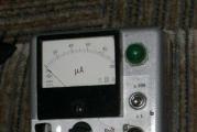
- To check, connect a light bulb;
- After connecting, the light bulb must be turned off - the triac must be cold;
- Connecting the resulting circuit to the grinder.
If the board is connected correctly, the triac and the angle grinder resistors should start smoothly, and the use of the speed should be regulated. After that, you can test the grinder in action. Similar knowledge may be needed when repairing motor malfunctions. For example, when the voltage rises or there is an incorrect balancing.
Do-it-yourself speed controller for a grinder
When using ingenuity to create a speed controller with your own hands, you can use soldered circuit boards for a sewing machine or vacuum cleaner controller. In addition, the components for the regulator are inexpensive and, if possible, they can be easily bought. It is worth noting that in the device the gearbox is necessary to support a certain number of revolutions and speed. If the speeds are increased, then the reason is most likely in the stator. The stator needs repair. Repairing the stator is possible at home.

The operation of the collector motor is provided by any kind of electrical voltage. When changing the voltage power, you need to reduce or increase the number of revolutions. It is the thyristor speed controller that helps to change this number.
Regulator assembly steps:
- First you need to unscrew the handle of the grinder, evaluate the place and figure out where to place the elements of the circuit (if there is no place, then you can make the device in a separate box);
- The resistor can be made of aluminum;
- Under the condition of slight heating of the triac, the radiator is small enough;
- Next comes the soldering of the structure.
In conclusion, there is sizing with epoxy resin for fixing. A homemade device can work for years. There are times when the device, after turning on, accelerates at higher speeds - this means that the stator winding is closed. In this case, a loop closure has occurred. The stator requires repair, most often it needs to be rewound.
What are the typical malfunctions: the winding breaks or burns, a short circuit occurs, an insulating surface breaks through.
Making a speed controller
An electric grinder is impossible without a speed controller so that it is possible to lower the speed.

The controller circuit from the point of view of physics looks like this:
- Resistor - R1;
- Trimmer resistor - VR1;
- Capacitor - C10;
- Triac - DIAC;
- Triac - TRIAC.
The electronic regulator is not only built-in, but also remote for convenience. In grinders from Bosch, electronics sets the speed from almost 3 thousand to 11.5 thousand. There is no load on the power of the meter, all indicators are taken into account. The tool will not make it difficult to reduce the number of revolutions and increase them. Adjustable speeds are simply necessary for any grinder work.
We make a soft start for a power tool with our own hands (video)
Only at first glance, it seems that the grinder may never be needed in life, that there will be no situations when it will come in handy, and even more so when it has to be repaired. Of course, you can turn to professionals, or you can determine the malfunction yourself and try to fix it.
If you have an old angle grinder in your arsenal, do not rush to write it off. Using a simple electrical circuit, the device can be easily upgraded by adding a speed change function to it. Thanks to a simple regulator, which you can really assemble with your own hands in a few hours, the functionality of the device will increase significantly. By reducing the rotational speed, the grinder can be used as a grinding and sharpening machine for various types of materials. There are new opportunities for the use of additional nozzles and equipment.
Why grinder low speed?
The built-in disc speed control function allows you to delicately process materials such as plastic or wood. At low speeds, the comfort and safety of work is increased. This function is especially useful in electrical and radio installation practice, in car services and restoration workshops.
In addition, among professional users of power tools there is a strong opinion that the simpler the device is, the more reliable it is. And it is better to take the additional service “minced meat” outside the power unit. In this scenario, the repair of equipment is greatly simplified. Therefore, some companies specifically produce remote separate electronic regulators that connect to the power cord of the machine.
Speed controller and soft start - what are you for?
In modern angle grinders, two important functions are used that increase the reliability and safety of the tool:
- speed controller - a device designed to change the number of engine revolutions in various operating modes;
- soft start - a scheme that provides a slow increase in engine speed from zero to maximum when the device is turned on.
They are used in electromechanical tools, in the design of which a collector motor is used. They help to reduce the wear of the mechanical part of the unit during switching on. Reduce the load on the electrical elements of the mechanism, starting them into operation gradually.
As studies of the properties of materials have shown, the most intensive development of rubbing nodes occurs during a sharp transition from a state of rest to a mode of rapid movement. For example, one start of an internal combustion engine in a car is equivalent in terms of piston group wear to 700 km of run.
When the power is turned on, there is an abrupt transition from a state of rest to rotation of the disk at a speed of 2.5-10 thousand revolutions per minute. Those who have worked with an angle grinder are well aware of the feeling that the machine is simply “pulling out of their hands”. It is at this moment that the vast majority of breakdowns associated with the mechanical part of the unit occur.
The stator and rotor windings also experience no less load. The collector motor starts in short circuit mode, the electromotive force is already pushing the shaft forward, but the inertia still does not allow it to rotate. There is a jump in the starting current in the coils of the electric motor. And although they are structurally designed for such work, sooner or later there comes a moment (for example, during a power surge in the network) when the winding insulation cannot withstand and an interturn short circuit occurs.
When soft start circuits and changes in engine speed are included in the electrical circuit of the tool, all of the above problems automatically disappear. Among other things, the problem of the “failure” of voltage in the general network at the time of starting the hand tool is being solved. And this means that the refrigerator, TV or computer will not be at risk of "burnout". And the safety circuit breakers on the meter will not work and turn off the current in the house or apartment.
The soft start circuit is used in angle grinders of medium and high price categories, the speed control unit is used mainly in professional angle grinder models.
Adjusting the speed allows you to process soft materials with a grinder, perform fine grinding and polishing - at high speed, wood or paint will simply burn out.
Additional wiring diagrams increase the cost of the tool, but increase the service life and level of safety during operation.
How to assemble a regulator circuit with your own hands
The simplest power regulator, suitable for a grinder, soldering iron or light bulb, is easy to assemble with your own hands.
Circuit diagram
In order to assemble the simplest speed controller for a grinder, you need to purchase the parts shown in this diagram.
Schematic diagram of the speed controller
- R1 - resistor, with a resistance of 4.7 kOhm;
- VR1 - tuning resistor, 500 kOhm;
- C1 - capacitor 0.1 uF x 400 V;
- DIAC - triac (symmetric thyristor) DB3;
- TRIAC - triac BT-136/138.
Circuit operation
Trimmer resistor VR1 changes the charging time of capacitor C1. When voltage is applied to the circuit, at the first moment of time (the first half-cycle of the input sinusoid), the triacs DB3 and TRIAC are closed. The output voltage is zero. Capacitor C1 is charged, the voltage across it rises. At a certain point in time, set by the R1-VR1 chain, the voltage on the capacitor exceeds the opening threshold of the triac DB3, the triac opens. The voltage from the capacitor is transmitted to the control electrode of the TRIAC triac, which also opens. A current begins to flow through an open triac. At the beginning of the second half-cycle of the sinusoid, the triacs close until the capacitor C1 recharges in the opposite direction. Thus, the output is a pulsed signal of complex shape, the amplitude of which depends on the operating time of the circuit C1-VR1-R1.
Assembly order
The assembly of this circuit will not make it difficult even for a beginner radio amateur. Spare parts are available, you can buy them at any store. Including soldering from old boards. The order of assembly of the regulator on thyristors is as follows:

How to connect the device to the angle grinder, options
The connection of the regulator depends on which type of device is selected. If a simple circuit is used, it is enough to mount it in the mains power supply channel of the power tool.
Installing a homemade board
There are no ready-made recipes for installation. Everyone who decides to equip the angle grinder with a regulator has it according to their goals and tool model. Someone inserts the device into the handle of the holder, someone into a special additional box on the case.
In different models, the space inside the grinder body can be different. In some, there is enough free space to install the control unit. In others, you have to bring it to the surface and fix it in a different way. But the trick is that, as a rule, there is always a certain cavity in the back of the instrument. It is designed for air circulation and cooling.
 Cavity at the back of the machine
 Usually this is where the factory speed controller is located. A hand-made circuit can be placed in this space. To prevent the regulator from burning out, thyristors should be installed on a radiator.
Video: soft start plus and engine speed control
Features of mounting the finished block
When buying and installing a factory regulator inside a grinder, most often you have to modify the case - cut a hole in it to bring out the adjusting wheel. But this can adversely affect the rigidity of the casing. Therefore, it is preferable to install the device outside.
The adjusting wheel changes speed
The numbers on the adjusting wheel indicate the number of revolutions of the spindle. The value is not absolute, but conditional. "1" - minimum speed, "9" - maximum. The rest of the figures serve as a guide for adjustment. The location of the wheel on the body is different. For example, on the angle grinder Bosch PWS 1300-125 CE, Wortex AG 1213-1 E or Watt WWS-900, it is located at the base of the handle. In other models, such as Makita 9565 CVL, the adjusting wheel is located at the end of the casing.
The connection diagram of the regulator to the angle grinder is not complicated, but sometimes it is not so easy to run the cables to the button, which is located on the other end of the device case. The problem can be solved by selecting the optimal wire section or bringing it to the surface of the casing.
The regulator is connected according to the diagram
A good option is to install the regulator on the surface of the device or attach it to a network cable. Not always everything works out on the first try, sometimes the device has to be tested, after which some adjustments must be made. And this is easier to do when access to its elements is open.
Important! If there is no experience with electrical circuits, it is more expedient to purchase a ready-made factory regulator or an angle grinder equipped with this function.
Power cord attachment
Device instruction manual
The basic rule when operating a grinder with a homemade speed controller is compliance with the regime of work and rest. The fact is that an engine running on a “regulated” voltage is especially hot. When grinding at low speeds, it is important to take frequent breaks so that the collector windings do not burn out.
It is also highly discouraged to turn on the tool if the speed control is set to a minimum - the reduced voltage will not be enough to scroll the rotor, the collector lamellas will remain in short circuit mode, the windings will start to overheat. Unscrew the variable resistor to the maximum, then, turning on the angle grinder, reduce the speed to the desired value.
Compliance with the correct order of switching on and adjustment will allow you to operate the angle grinder indefinitely.
In addition, it should be understood that the adjustment of the speed of rotation on the angle grinder occurs according to the principle of a water tap. The device does not increase the number of revolutions, it can only lower them. It follows from this that if the maximum passport speed is 3000 rpm, then when the speed controller is connected, the angle grinder will work in a range lower than the maximum speed.
Attention! If the angle grinder already contains electronic circuits, for example, it is already equipped with a speed controller, then the thyristor controller will not work. The internal circuits of the device simply will not turn on.
Video: homemade angle grinder speed controller
Equipping the grinder with an engine speed control circuit will increase the efficiency of using the device. and expand its functional range. It will also save the technological resource of the grinding machine and increase its service life.
www.techznatok.com
Speed regulator for grinders: how to reduce speed and make a soft start
The power tool in our workshop occupies one of the main places. Each electrical device performs all functions according to technical data. What else would you like? I really want the tool to not fail longer or not break at all. As a person gets used to a friend - a dog, so he gets used to an instrument.

One of the main tools is an angle grinder, which we call a grinder. This is a versatile tool that can cut, grind, clean the surface, saw boards and can be adapted to many other operations.
Soft start and speed control + (Video)
A smooth start of a power tool is the main guarantee of its longevity. Do you remember when a light bulb burns out? Most often at the moment of inclusion. Because after connecting to the electrical network, the load increases sharply. The underworked places of the spiral do not withstand and it burns out.
The same processes take place in Bulgarian. At the moment of switching on, the current increases sharply, because the driving forces must not only move the armature from its place, but also quickly gain the necessary speed. The effect of such a hard start can be the most deplorable - a winding break.
To reduce the likelihood of tool failure due to a hard start, it is necessary to modify the grinder and provide it with a small built-in soft starter.
Another improvement is the rotation regulator. Everyone knows from their own experience how inconvenient it is to work with a tool that does not have rotation adjustment. If the electric drill does not have such a device, then it is difficult to choose the rotation speed and feed of the drill. This leads either to jamming of the drill or to its breakage.
A lathe works in a similar way, in which there is a whole set of special gears for adjusting the rotation of the spindle. Not only the safety of the cutter, but also the quality of material processing largely depends on this.
You can combine two advantages - soft start and shaft speed control using an electronic circuit. It is quite possible to assemble it with your own hands and install it directly into the machine body. With such a scheme, it will start smoothly without creating overloads in the windings and the network. And with the same scheme, it will be possible to adjust the speed in order to select the mode of operation with any material.

If you cut metal with a significant thickness and hardness, then you need to maintain high speeds. But when processing surfaces of low-melting materials, high speed will do more harm than good. It must be reduced. At high speed it is dangerous to work with a stone or a tile. And here it must be reduced.
Even when grinding the disc, the rotation speed must be proportionally changed, because the linear speed of the edge of the disc will decrease. You can’t do without a speed controller when working with a diamond-cut disk, because at high temperature it collapses very quickly.
Everything suggests that if the grinder does not have a speed controller, then it must be made and installed in the car.
How to make a speed controller with your own hands + (Video)
In order not to complicate the perception of the principle of operation in complex terms, the principle operation of the circuit can be explained simply. It has a sensing element that reads the load value. Depending on the read value, this element controls the locking device.
The principle of operation is similar to the operation of a water tap. In this case, you are the sensor that controls the faucet. The flow of water, depending on the need, becomes either more or less. The same process occurs with current.
It is necessary to correctly understand the moment that we will not be able to increase the rotation speed more than that indicated in the characteristics of the angle grinder. We can only lower turnover. If the maximum rpm is 3000, then the range in which we can adjust the rpm will be below this value.
In the simplest version, you can use a thyristor regulator circuit. He will both feel and regulate. Two in one. This scheme has only five parts. It is very compact and fits easily into a case. Such a regulator will not work from zero speed, but this is not necessary for the grinder.
If lower speeds are needed in the work, then it is necessary to use another circuit on an integrated circuit, where the triac will be the locking element. Such a scheme will be able to regulate the speed from almost zero to the desired value.

In both schemes, the main load falls on the locking element. It must be rated for voltages up to 600 V and currents up to 12 A. If your grinder is more powerful than 1 kW, then the locking element must withstand loads up to 20 A.
All details of the circuit on the thyristor can be placed on a printed circuit board or simply surface mounted. According to the second option, the parts are soldered on the printed circuit board. The printed circuit board can be manufactured in different ways. It can be etched from foil textolite, you can even cut it out with a cutter, but it will turn out very rough. In principle, you can ask her to make a familiar radio amateur for a very modest reward.

Radio-electronic elements are inserted into the printed circuit board. They can be purchased at specialized stores or radio markets. The ratings of each should not differ in face value and in rated power. It is desirable to install a thyristor or triac on a heat sink - an aluminum or copper radiator.

When the finished board is ready, you need to choose a convenient place in the grinder case to install it. It is desirable to install it so that it is convenient to use, and so that it does not interfere with the work process.

Before installing the circuit in the car, it must be checked. To do this, instead of a grinder, you need to connect an ordinary incandescent lamp to the output. An instance with a power of 60 - 40 W at 220 V is suitable. Performance will be obvious by changing the glow of the light bulb.

Now it remains to mount the device in the chosen place and make a trial run of the grinder. It will stop escaping from your hands during start-up, and the speed will be smoothly regulated by turning the knob.
instrument-blog.ru
How to make a speed controller for a grinder with your own hands, how to reduce or increase speed + video instruction
Do you have a grinder, but no speed controller? You can make it yourself.
Speed controller and soft start for grinder
Both are necessary for reliable and convenient operation of the power tool.
What is a speed controller and what is it for?
This device is designed to control the power of an electric motor. With it, you can adjust the speed of rotation of the shaft. The numbers on the adjusting wheel indicate the change in disc speed.

grinder speed controller
The regulator is not installed on all angle grinders.
Bulgarians with a speed controller: examples in the photo
Herz HZ-AG125EV Stayer SAG-125–900 Makita 9562CVH Flex LE 9–10 125 Bosch PWR 180 CE ASpro ASpro-A1 Hitachi G14DSL Metabo PE 12–175 DeWALT DCG412M2 EIBENSTOCK EWS 400The lack of a regulator greatly limits the use of the grinder. The speed of rotation of the disc affects the quality of the grinder and depends on the thickness and hardness of the material being processed.
If the speed is not regulated, then the speed is constantly kept at maximum. This mode is only suitable for hard and thick materials such as angle, pipe or profile. Reasons why a regulator is necessary:
- For thin metal or soft wood, a lower rotation speed is needed. Otherwise, the edge of the metal will melt, the working surface of the disk will become blurry, and the wood will turn black from high temperature.
- For cutting minerals, it is necessary to regulate the speed. Most of them break off small pieces at high speed and the cut becomes uneven.
- You do not need the highest speed to polish cars, otherwise the paintwork will deteriorate.
- To change the disk from a smaller diameter to a larger one, you need to reduce the speed. It is almost impossible to hold a grinder with a large disk rotating at high speed with your hands.
- Diamond blades must not be overheated so as not to spoil the surface. For this, the turnover is reduced.
Why you need a soft start
The presence of such a launch is a very important point. When you start a powerful power tool connected to the network, an inrush current occurs, which is many times higher than the rated current of the motor, the voltage in the network sags. Although this surge is short-lived, it causes increased wear on the brushes, the motor commutator, and all parts of the tool through which it flows. This can cause failure of the tool itself, especially the Chinese one, with unreliable windings that can burn out at the most inopportune moment during switching on. And also there is a large mechanical jerk at startup, which leads to rapid wear of the gearbox. This start prolongs the life of the power tool and increases the level of comfort when working.
Electronic unit in angle grinder
The electronic unit allows you to combine the speed controller and soft start into one. The electronic circuit is implemented according to the principle of pulse-phase control with a gradual increase in the opening phase of the triac. Such a block can be supplied with grinders of different capacities and price categories.
Varieties of devices with an electronic unit: examples in the table
Angle grinders with an electronic unit: popular in the photo
Felisatti AG125/1000S Bosch GWS 850 CE Makita SA5040C Makita PC5001C Flex LST 803 VRDIY speed controller
The speed controller is not installed in all models of grinders. You can make a block for speed control with your own hands or purchase a ready-made one.
Factory speed controllers for angle grinders: photo examples
Bosh grinder speed controller Bosh grinder speed controller Sturm grinder speed controller DWT grinder speed controller DWT grinder speed controllerSuch regulators have a simple electronic circuit. Therefore, creating an analogue with your own hands will not be difficult. Consider what the speed controller for grinders up to 3 kW is assembled from.
PCB manufacturing
The simplest scheme is shown below.

The simplest circuit of the speed controller
Since the circuit is very simple, it makes no sense to install a computer program for processing electrical circuits because of it alone. Moreover, special paper is needed for printing. And not everyone has a laser printer. Therefore, let's go by the simplest way of manufacturing a printed circuit board.
Take a piece of textolite. Cut off the required size for the chip. Sand the surface and degrease. Take a marker for laser discs and draw a diagram on the textolite. In order not to be mistaken, first draw with a pencil. Next, let's start etching. You can buy ferric chloride, but after it the sink is poorly washed. If you accidentally drip on clothes, stains will remain that cannot be completely removed. Therefore, we will use a safe and cheap method. Prepare a plastic container for the solution. Pour in 100 ml of hydrogen peroxide. Add half a tablespoon of salt and a sachet of citric acid to 50 g. The solution is made without water. You can experiment with proportions. And always make a fresh solution. Copper should be all etched. This takes about an hour. Rinse the board under a stream of well water. Drill holes.
It can be made even easier. Draw a diagram on paper. Glue it with adhesive tape to the cut out textolite and drill holes. And only after that draw the circuit with a marker on the board and poison it.
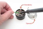
Wipe the board with an alcohol - rosin flux or a regular solution of rosin in isopropyl alcohol. Take some solder and tin the tracks.
Mounting of electronic components (with photo)
Prepare everything you need to mount the board:

Bite off four pins and solder them to the board. Then install the dinistor and all other parts except for the variable resistor. Solder the triac last. Take a needle and a brush. Clean the gaps between the tracks to remove possible short circuits. Triac free end with a hole is mounted on an aluminum radiator for cooling. Clean the area where the element is attached with fine sandpaper. Take the KPT-8 heat-conducting paste and apply a small amount of paste on the radiator. Secure the triac with a screw and nut. Since all the details of our design are under mains voltage, we will use a handle made of insulating material for adjustment. Put it on a variable resistor. With a piece of wire, connect the extreme and middle terminals of the resistor. Now solder two wires to the extreme conclusions. Solder the opposite ends of the wires to the corresponding pins on the board.
You can make the entire installation hinged. To do this, we solder the parts of the microcircuit to each other directly using the legs of the elements themselves and the wires. Here, too, you need a radiator for the triac. It can be made from a small piece of aluminum. Such a regulator will take up very little space and can be placed in the grinder case.
If you want to install an LED indicator in the speed controller, then use a different scheme.
Regulator circuit with LED indicator.

Regulator circuit with LED indicator
Diodes added here:
- VD 1 - diode 1N4148;
- VD 2 - LED (operation indication).
Assembled controller with LED.

Assembled controller with LED
This block is designed for low-power grinders, so the triac is not installed on the radiator. But if you use it in a powerful tool, then do not forget about the aluminum heat transfer board and the bta16 triac.
Making a power regulator: video
Electronic unit test
Before connecting the block to the instrument, we will test it. Get an overhead socket. Insert two wires into it. Connect one of them to the board, and the second to the network cable. The cable has one more wire left. Connect it to the network board. It turns out that the regulator is connected in series to the load power circuit. Connect a lamp to the circuit and check the operation of the device.
Connecting the regulator to the grinder
The speed controller is connected to the tool in series.
The connection diagram is shown below.

Connection diagram to the angle grinder
If there is free space in the handle of the grinder, then our block can be placed there. The circuit, assembled by surface mounting, is glued with epoxy resin, which serves as an insulator and protection against shaking. Pull the variable resistor with a plastic handle out to adjust the speed.
Installing the regulator inside the angle grinder body: video
The electronic unit, assembled separately from the grinder, is placed in a case made of insulating material, since all elements are under mains voltage. A portable socket with a network cable is screwed to the body. The handle of the variable resistor is brought out.

Speed controller in a box
The regulator is connected to the network, and the tool is connected to a portable socket.
Speed regulator for a grinder in a separate case: video
Usage
There are a number of recommendations for the correct use of an angle grinder with an electronic unit. When starting the tool, let it accelerate to the set speed, do not rush to cut anything. After turning it off, restart it after a few seconds so that the capacitors in the circuit have time to discharge, then the restart will be smooth. You can adjust the speed while the grinder is running by slowly turning the knob of the variable resistor.
A grinder without a speed controller is good because without serious expenses you can make a universal speed controller for any power tool yourself. The electronic unit, mounted in a separate box, and not in the body of the grinder, can be used for a drill, drill, circular saw. For any tool with a commutator motor. Of course, it is more convenient when the control knob is on the tool, and you don’t have to go anywhere and bend over to turn it. But now it's up to you to decide. It's a matter of taste.
legkovmeste.ru
A grinder with a speed controller has more options than a simpler version of a power tool.
If the grinder is not equipped with a speed controller, can I install it myself? Most angle grinders (angle grinders), in common grinders, have a speed controller.
 The speed controller is located on the angle grinder body
 Consideration of various adjustments should begin with an analysis of the electrical circuit of the angle grinder.
The simplest representation of the electrical circuit of a grinder
More advanced models automatically maintain the rotation speed regardless of the load, but tools with manual disc speed control are more common. If a trigger-type regulator is used on a drill or an electric screwdriver, then such a regulation principle is not possible on an angle grinder. Firstly, the features of the tool suggest a different grip when working. Secondly, adjustment during operation is unacceptable, therefore, the speed value is set with the engine turned off.
Why regulate the speed of rotation of the grinder disk at all?
- When cutting metal of different thicknesses, the quality of work is highly dependent on the speed of rotation of the disk. When cutting hard and thick material, it is necessary to maintain the maximum rotation speed. When processing thin sheet metal or soft metal (for example, aluminum), high speeds will lead to edge melting or rapid blurring of the working surface of the disc;
- Cutting and cutting stone and tiles at high speed can be dangerous. In addition, a disc that spins at high speed knocks out small pieces from the material, making the cut surface chipped. Moreover, different speeds are selected for different types of stone. Some minerals are just processed at high speeds;
- Grinding and polishing is basically impossible without speed control. By setting the speed incorrectly, you can spoil the surface, especially if it is a paintwork on a car or a material with a low melting point;
- The use of discs of different diameters automatically implies the mandatory presence of a regulator. Changing the disk Ø115 mm to Ø230 mm, the rotation speed must be reduced by almost half. Yes, and holding an angle grinder with a 230 mm disk rotating at a speed of 10,000 rpm is almost impossible;
- Polishing of stone and concrete surfaces, depending on the type of crowns used, is carried out at different speeds. Moreover, when the rotation speed decreases, the torque should not decrease;
- When using diamond discs, it is necessary to reduce the number of revolutions, since their surface quickly fails due to overheating. Of course, if your angle grinder only works as a cutter for pipes, angles and profiles, a speed controller is not required. And with the universal and versatile use of angle grinders, it is vital.
Typical speed controller circuit
 This is what the controller board looks like
 The engine speed controller is not just a variable resistor that lowers the voltage. An electronic control of the current strength is required, otherwise, with a drop in speed, the power will decrease proportionally, and, accordingly, the torque. In the end, a critically low voltage value will come, when, at the slightest resistance of the disk, the electric motor simply cannot turn the shaft. Therefore, even the simplest regulator must be calculated and implemented in the form of a well-developed scheme.
And more advanced (and therefore expensive) models are equipped with regulators based on an integrated circuit.
Integrated circuit of the regulator. (most advanced)
If we consider the electrical circuit of the angle grinder in principle, then it consists of a speed controller and a soft start module. Power tools equipped with advanced electronic systems are significantly more expensive than their simple counterparts. Therefore, not every home master is able to purchase such a model. And without these electronic blocks, only the winding of the electric motor and the power key will remain.
The reliability of modern electronic components of the angle grinder exceeds the life of the motor windings, so do not be afraid to purchase a power tool equipped with such devices. The limiter can only be the price of the product. Moreover, users of inexpensive models without a regulator sooner or later come to install it themselves. The block can be purchased ready-made or made independently.
Making a speed controller with your own hands
Attempts to adapt a conventional dimmer to adjust the brightness of the lamp will not work. First, these devices are designed for a completely different load. Secondly, the principle of operation of the dimmer is not compatible with the control of the motor winding. Therefore, you have to mount a separate circuit, and figure out how to place it in the tool case. IMPORTANT! If you do not have the skills to work with electrical circuits, it is better to purchase a ready-made factory regulator, or an angle grinder with this function.
 Homemade speed controller
 The simplest thyristor speed controller can be easily made by yourself. To do this, you need five radio elements, which are sold on any radio market.
Wiring diagram of thyristor speed controller for your tool
The compact design allows you to place the circuit in the angle grinder housing without compromising ergonomics and reliability. However, this scheme does not allow you to maintain torque when the speed drops. The option is suitable for reducing speed when cutting thin sheet metal, carrying out polishing work, and processing soft metals.
If your angle grinder is used for stone processing, or you can install disks larger than 180 mm on it, you need to assemble a more complex circuit, where the KR1182PM1 chip, or its foreign equivalent, is used as a control module.
 Speed control wiring diagram using the KR1182PM1 microcircuit
 Such a circuit controls the current strength at any speed, and minimizes the loss of torque when they decrease. In addition, this scheme treats the engine more carefully, extending its life.
The question of how to adjust the speed of the tool arises when it is stationary. For example, when using a grinder as a circular saw. In this case, the connection point (automatic or socket) is equipped with a regulator, and the speed is adjusted remotely.
Regardless of the execution method, the angle grinder speed controller expands the capabilities of the tool and adds comfort when using it.
Do you have a grinder, but no speed controller? You can make it yourself.
Speed controller and soft start for grinder
Both are necessary for reliable and convenient operation of the power tool.
What is a speed controller and what is it for?
This device is designed to control the power of an electric motor. With it, you can adjust the speed of rotation of the shaft. The numbers on the adjusting wheel indicate the change in disc speed.
The regulator is not installed on all angle grinders.
Bulgarians with a speed controller: examples in the photo


The lack of a regulator greatly limits the use of the grinder. The speed of rotation of the disc affects the quality of the grinder and depends on the thickness and hardness of the material being processed.
If the speed is not regulated, then the speed is constantly kept at maximum. This mode is only suitable for hard and thick materials such as angle, pipe or profile. Reasons why a regulator is necessary:
- For thin metal or soft wood, a lower rotation speed is needed. Otherwise, the edge of the metal will melt, the working surface of the disk will become blurry, and the wood will turn black from high temperature.
- For cutting minerals, it is necessary to regulate the speed. Most of them break off small pieces at high speed and the cut becomes uneven.
- You do not need the highest speed to polish cars, otherwise the paintwork will deteriorate.
- To change the disk from a smaller diameter to a larger one, you need to reduce the speed. It is almost impossible to hold a grinder with a large disk rotating at high speed with your hands.
- Diamond blades must not be overheated so as not to spoil the surface. For this, the turnover is reduced.
Why you need a soft start
The presence of such a launch is a very important point. When you start a powerful power tool connected to the network, an inrush current occurs, which is many times higher than the rated current of the motor, the voltage in the network sags. Although this surge is short-lived, it causes increased wear on the brushes, the motor commutator, and all parts of the tool through which it flows. This can cause failure of the tool itself, especially the Chinese one, with unreliable windings that can burn out at the most inopportune moment during switching on. And also there is a large mechanical jerk at startup, which leads to rapid wear of the gearbox. This start prolongs the life of the power tool and increases the level of comfort when working.
Electronic unit in angle grinder
The electronic unit allows you to combine the speed controller and soft start into one. The electronic circuit is implemented according to the principle of pulse-phase control with a gradual increase in the opening phase of the triac. Such a block can be supplied with grinders of different capacities and price categories.
Varieties of devices with an electronic unit: examples in the table
Angle grinders with an electronic unit: popular in the photo


DIY speed controller
The speed controller is not installed in all models of grinders. You can make a block for speed control with your own hands or purchase a ready-made one.
Factory speed controllers for angle grinders: photo examples

 Bosh grinder speed controller
  Speed regulator grinders Sturm
 DWT angle grinder speed controller
Such regulators have a simple electronic circuit. Therefore, creating an analogue with your own hands will not be difficult. Consider what the speed controller for grinders up to 3 kW is assembled from.
PCB manufacturing
The simplest scheme is shown below.
Since the circuit is very simple, it makes no sense to install a computer program for processing electrical circuits because of it alone. Moreover, special paper is needed for printing. And not everyone has a laser printer. Therefore, let's go by the simplest way of manufacturing a printed circuit board.
Take a piece of textolite. Cut off the required size for the chip. Sand the surface and degrease. Take a marker for laser discs and draw a diagram on the textolite. In order not to be mistaken, first draw with a pencil. Next, let's start etching. You can buy ferric chloride, but after it the sink is poorly washed. If you accidentally drip on clothes, stains will remain that cannot be completely removed. Therefore, we will use a safe and cheap method. Prepare a plastic container for the solution. Pour in 100 ml of hydrogen peroxide. Add half a tablespoon of salt and a sachet of citric acid to 50 g. The solution is made without water. You can experiment with proportions. And always make a fresh solution. Copper should be all etched. This takes about an hour. Rinse the board under a stream of well water. Drill holes.
It can be made even easier. Draw a diagram on paper. Glue it with adhesive tape to the cut out textolite and drill holes. And only after that draw the circuit with a marker on the board and poison it.
Wipe the board with an alcohol - rosin flux or a regular solution of rosin in isopropyl alcohol. Take some solder and tin the tracks.
Mounting of electronic components (with photo)
Prepare everything you need to mount the board:
- Solder coil.
- Pins in the board.
- Triac bta16.
- Capacitor 100 nF.
- 2 kΩ fixed resistor.
- Dinistor db3.
- Variable resistor with a linear dependence of 500 kOhm.
Bite off four pins and solder them to the board. Then install the dinistor and all other parts except for the variable resistor. Solder the triac last. Take a needle and a brush. Clean the gaps between the tracks to remove possible short circuits. Triac free end with a hole is mounted on an aluminum radiator for cooling. Clean the area where the element is attached with fine sandpaper. Take the KPT-8 heat-conducting paste and apply a small amount of paste on the radiator. Secure the triac with a screw and nut. Since all the details of our design are under mains voltage, we will use a handle made of insulating material for adjustment. Put it on a variable resistor. With a piece of wire, connect the extreme and middle terminals of the resistor. Now solder two wires to the extreme conclusions. Solder the opposite ends of the wires to the corresponding pins on the board.
You can make the entire installation hinged. To do this, we solder the parts of the microcircuit to each other directly using the legs of the elements themselves and the wires. Here, too, you need a radiator for the triac. It can be made from a small piece of aluminum. Such a regulator will take up very little space and can be placed in the grinder case.
If you want to install an LED indicator in the speed controller, then use a different scheme.
Regulator circuit with LED indicator.
Diodes added here:
- VD 1 - diode 1N4148;
- VD 2 - LED (operation indication).
Assembled controller with LED.
This block is designed for low-power grinders, so the triac is not installed on the radiator. But if you use it in a powerful tool, then do not forget about the aluminum heat transfer board and the bta16 triac.
Making a power regulator: video
Electronic unit test
Before connecting the block to the instrument, we will test it. Get an overhead socket. Insert two wires into it. Connect one of them to the board, and the second to the network cable. The cable has one more wire left. Connect it to the network board. It turns out that the regulator is connected in series to the load power circuit. Connect a lamp to the circuit and check the operation of the device.
Testing the power regulator with a tester and a lamp (video)
Connecting the regulator to the grinder
The speed controller is connected to the tool in series.
The connection diagram is shown below.
If there is free space in the handle of the grinder, then our block can be placed there. The circuit, assembled by surface mounting, is glued with epoxy resin, which serves as an insulator and protection against shaking. Pull the variable resistor with a plastic handle out to adjust the speed.
Installing the regulator inside the angle grinder body: video
The electronic unit, assembled separately from the grinder, is placed in a case made of insulating material, since all elements are under mains voltage. A portable socket with a network cable is screwed to the body. The handle of the variable resistor is brought out.
The regulator is connected to the network, and the tool is connected to a portable socket.
Speed regulator for a grinder in a separate case: video
Usage
There are a number of recommendations for the correct use of an angle grinder with an electronic unit. When starting the tool, let it accelerate to the set speed, do not rush to cut anything. After turning it off, restart it after a few seconds so that the capacitors in the circuit have time to discharge, then the restart will be smooth. You can adjust the speed while the grinder is running by slowly turning the knob of the variable resistor.
A grinder without a speed controller is good because without serious expenses you can make a universal speed controller for any power tool yourself. The electronic unit, mounted in a separate box, and not in the body of the grinder, can be used for a drill, drill, circular saw. For any tool with a commutator motor. Of course, it is more convenient when the control knob is on the tool, and you don’t have to go anywhere and bend over to turn it. But now it's up to you to decide. It's a matter of taste.
All budget options for angle grinders have several drawbacks. First, there is no soft start system. This is a very important option. Surely all of you have included this powerful power tool in the network, and when you start it, you have watched the glow of the light bulb, which is also connected to this network, drop.
This phenomenon occurs for the reason that powerful electric motors at the time of startup consume huge currents, due to which the mains voltage sags. This can destroy the tool itself, especially Chinese-made ones with unreliable windings that may one day burn out during start-up.
That is, the soft start system will protect both the network and the instrument. In addition, at the moment the tool is launched, a powerful recoil or push occurs, and in the case of a soft start system, this, of course, will not happen.
Secondly, there is no speed controller, which will allow you to work with the tool for a long time without loading it.
The diagram below is from an industrial design:
It is introduced by the manufacturer into expensive devices.
You can connect to the circuit not only the "grinder", but, in principle, any devices - a drill, milling and turning machines. But taking into account the fact that the collector motor should be in the tool.
With asynchronous motors, this will not work. It needs a frequency converter.
So, you need to make a printed circuit board and proceed with the assembly.
A dual operational amplifier LM358 is used as a regulatory element, which controls a power triac using a transistor VT1.
So, the power link in this circuit is a powerful triac of the BTA20-600 type.
There was no such triac in the store and I had to buy BTA28. It is slightly more powerful than what is according to the scheme. In general, for engines with a power of up to 1 kW, you can use any triac with a voltage of at least 600 V and a current of 10-12 A. But it is better to have some margin and take 20 A triacs, they still cost a penny.
During operation, the triac will heat up, so it is necessary to install a heat sink on it.
So that there are no questions about the fact that the motor at start-up can consume currents that significantly exceed the maximum current of the triac, and the latter can simply burn out, remember that the circuit has a soft start, and starting currents can be ignored.
Surely everyone is familiar with the phenomenon of self-induction. This effect is observed when opening a circuit to which an inductive load is connected.
The same is true for this diagram. When the power supply to the motor abruptly stops, the self-induction current from it can burn the triac. And the snubber circuit dampens the self-induction.
The resistor in this circuit has a resistance of 47 to 68 ohms, and a power of 1 to 2 watts. Film capacitor for 400 V. In this embodiment, self-induction as a side effect.
Resistor R2 provides current suppression for the low voltage control circuit.
The circuit itself, to some extent, is both a load and a stabilizing link. Due to this, after the resistor, you can not stabilize the power. Although the network has the same circuits with an additional zener diode, it is pointless to use it, since the voltage at the power supply terminals of the operational amplifier is within normal limits.
Possible replacement options for low-power transistors can be seen in the following picture:
The circuit board mentioned earlier is only a board for the soft starter and does not contain any speed control components. This is done on purpose, because in any case, the regulator must be output using wires.
The regulator is tuned using a 100 kΩ multi-turn trimmer.
If you need a more powerful regulator, then it can be assembled according to the following scheme:
If everything is in order, then after disconnecting from the network, you immediately need to check the triac by touch - it should be cold.
If everything is working fine - the "grinder" starts smoothly, and the speed is regulated, then it's time to start testing under load.
Attached files:
Scheme for connecting an analog CCTV camera to a TV, computer Connecting a digital video surveillance camera